The useful starting point
A drive is part of a motor system. The useful specification joins the process requirement, motor, power supply, cable, controls and protection into one operating envelope.
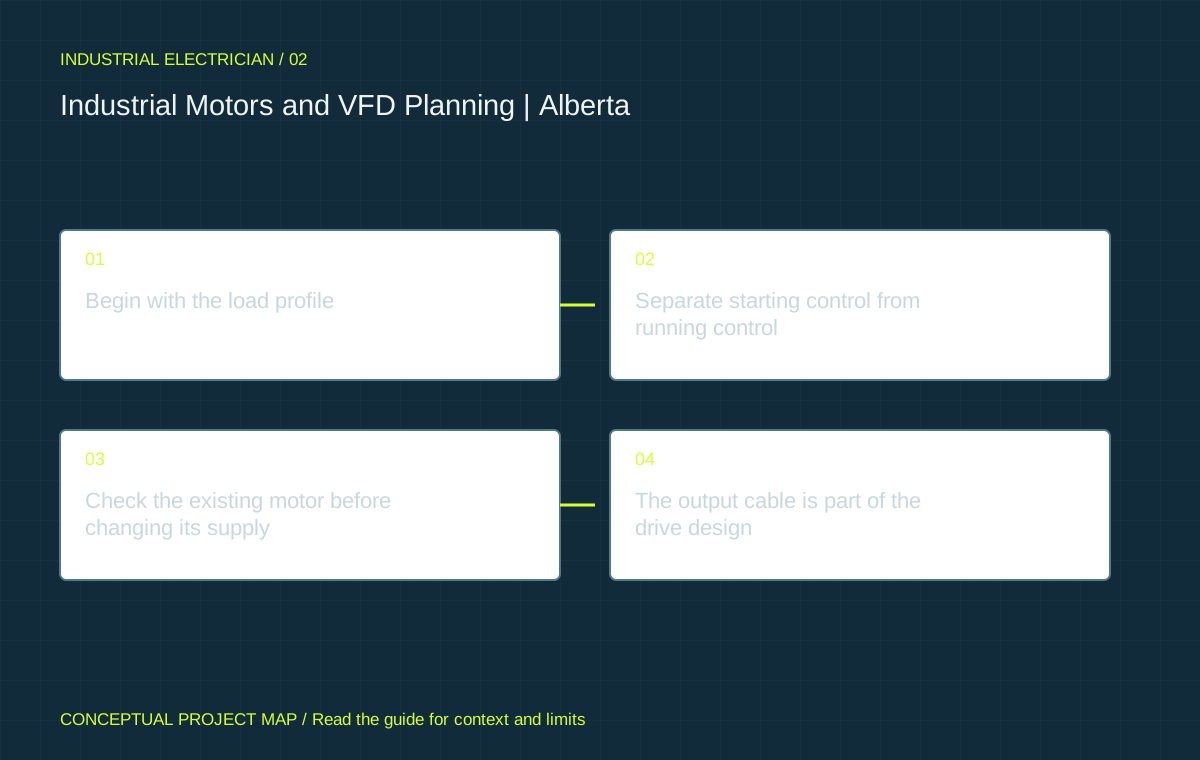
Begin with the load profile
Describe what the driven equipment must do: move a fixed volume, maintain a pressure, control a conveyor speed, lift a load or operate a compressor through a duty cycle. Record the operating range, starts, stop method, overload events and process constraints. Two motors with identical nameplate power can need very different drive arrangements because their loads behave differently.
For a pump or fan, identify whether demand varies and how it is currently controlled. A throttling valve, bypass or damper may create an opportunity for speed control, but process requirements can limit the usable range. A positive-displacement pump, loaded conveyor and centrifugal fan cannot be treated as the same energy case. The often-quoted speed-cubed relationship is an idealised variable-torque model, not a savings guarantee for any rotating machine.
Natural Resources Canada recommends assessing the process and existing system before selecting a VFD. Bring operating observations and, where available, trend data to that assessment. A measured duty profile is more useful than assuming the motor runs at its nameplate output throughout every shift.
Separate starting control from running control
An across-the-line starter, soft starter and variable frequency drive solve different problems. A conventional starter provides a simple operating arrangement where the mechanical system and supply can tolerate the start. A soft starter controls the start and, for suitable equipment, the stop; it does not normally provide continuous process speed control. A VFD controls the supplied frequency and voltage to regulate motor operation through the required range.
The selection should consider starting torque, acceleration time, load inertia, repeated starts, stopping behaviour and the effect on the electrical system. Reducing starting current is useful only if the motor can still accelerate the actual load. A drive selected solely from the motor’s power rating can be unsuitable for the overload duty or ambient conditions. The application’s current and overload envelope must be checked against the manufacturer’s ratings.
Define the operating modes: local control, remote automatic operation, manual fallback and maintenance. State which commands are permitted in each mode and how loss of a reference or communications link is handled. Do not assume that a bypass starter is a safe or compatible fallback for every process. Its electrical, mechanical and control implications need a separate review.
Check the existing motor before changing its supply
Collect the motor’s full nameplate and manufacturer information, including voltage, current, speed, insulation and enclosure. Document age, repair history, existing thermal protection, bearing arrangement and the driven machine. A label describing a motor as suitable for inverter duty does not remove every application limit. The required speed range, loading, cooling and cable conditions still matter.
Reduced speed can reduce the cooling provided by a shaft-mounted fan. A process that demands high torque for long periods at low speed may need a different motor or independent cooling. Mechanical resonance, lubrication and driven-equipment limits may also exclude parts of the proposed speed range. NRCan’s motor reference guide discusses cooling and mechanical considerations for variable-speed operation.
Identify who approves motor and mechanical compatibility. The electrical contractor can verify installation requirements, while the motor supplier and process-equipment manufacturer may need to confirm the operating envelope. This is particularly important when a legacy machine has no complete manual or when an existing motor has been rewound. Record unresolved assumptions before buying the drive.
The output cable is part of the drive design
A PWM drive changes the electrical environment of the cable and motor. Cable construction, length, routing, shield termination and bonding can affect performance. Do not transplant a single cable-length limit from an unrelated drive family. The selected drive’s current manual and the actual motor-cable combination are the relevant starting points.
Rockwell Automation’s PowerFlex guidance directs designers to product-specific cable and grounding requirements. Those documents are examples of manufacturer guidance, not generic installation rules for every brand. Where cable length, reflected voltage effects or common-mode behaviour are a concern, the designer should assess the appropriate output treatment rather than adding a filter by habit.
Survey the complete route before pricing. Include transitions through walls, tray condition, segregation from sensitive signals, mechanical exposure and access for installation. A drive near the electrical room may simplify power distribution while a drive near the motor may shorten its output cable. Compare both arrangements with environment, service access, controls wiring and maintenance requirements.
Look upstream as well as downstream
Drives can change the supply’s current waveform and affect the distribution system. The importance depends on the drive topology, system impedance, other loads and existing equipment. A facility adding many drives should assess the combined operating case; evaluating each unit in isolation can miss interactions at the common bus.
Document the supply configuration, transformer capacity, existing power-factor equipment and any history of nuisance trips or overheating. A capacitor bank intended to improve power factor is not automatically compatible with a growing population of nonlinear loads. The power quality guide explains why measured true power factor, harmonic behaviour and process events should be considered together.
Ambient temperature, enclosure ventilation, dust and washdown also belong in the specification. An enclosure that protects electronics from contamination can trap heat unless its thermal design is addressed. Assess the drive at the required duty and site conditions. Do not select an enclosure rating from a photograph or treat the general plant temperature as the temperature inside the cabinet.
Define the interfaces that production depends on
List each command, feedback and interlock with its owner and expected failure behaviour. The process may depend on speed feedback, ready status, permissives, pressure signals and an upstream or downstream sequence. The controls programme needs enough detail to distinguish “drive available” from “machine safe and ready to run.”
Safety functions require their own competent design and validation. A network stop command, standard PLC instruction or drive fault indication cannot be assumed to perform the required safety function. The project should identify the machinery-safety specialist, required performance basis and validation evidence where safety-related functions are modified. This portal does not provide a safety-circuit design.
For replacements, preserve a controlled copy of the approved parameters and software, record the running revisions and decide how the restored configuration will be checked. An uploaded parameter file can still contain the wrong motor data or process limit. Commissioning must verify the intended operation on the real machine, under an approved test plan.
Model energy with transparent assumptions
The motor energy scenario tool compares operating cases using user-entered power, load, efficiency, hours and energy rate. It does not estimate savings from speed alone. Treat the result as a discussion model until input power and operating time are measured. Demand charges, power-factor provisions, downtime, maintenance and production effects need separate treatment.
Include the complete project cost when assessing a drive: engineering, equipment, enclosure cooling, cabling, possible supply treatment, programming, installation, commissioning and shutdown. A favourable electricity calculation cannot justify a process that becomes unstable or loses its approved operating range. For a fixed-duty load with little scope to reduce useful output, a VFD may primarily improve control rather than reduce energy use.
Ask for acceptance criteria tied to the process: stable pressure or flow, permitted acceleration, acceptable operating temperatures, fault behaviour and usable control modes. A successful no-load run is only one part of acceptance. Retain the baseline and first operating records so later troubleshooting can distinguish an installation defect from a changed process condition.
Questions / Direct answers
Common questions
Does every industrial motor benefit from a VFD?
No. Assess the required process duty, usable speed range, existing controls and complete project cost. Variable demand can create an opportunity; a fixed process duty may offer little energy reduction even when speed control improves operation.
Can a soft starter control running speed?
A conventional soft starter is mainly a starting and stopping control. It should not be specified as a substitute for continuous speed regulation. Confirm the exact product and application with the designer.
Can an old motor be connected to a new VFD?
Possibly, but the motor, insulation, cooling, bearings, cable arrangement and required speed range need review. A successful brief test does not establish suitability throughout the production duty.
How much energy will a VFD save?
There is no honest universal percentage. Use the actual process profile and measured or supported input-power assumptions, then include drive losses and operational constraints. Validate the result against operating data.
Does the current calculator size a motor feeder?
No. It estimates steady balanced running current from entered assumptions. Conductor sizing, motor rules, overloads, short-circuit protection and starting duty require code-based design.
References / Jurisdiction matters
Sources & further reading
Confirm the actual location, permit authority and equipment instructions before relying on a requirement. A source from another jurisdiction is identified for context.
- Variable frequency drives: application and process assessmentNatural Resources Canada · 2026-10-07
- Variable frequency drives: energy efficiency reference guideNatural Resources Canada · 2026-10-07
- Electric motors: energy efficiency reference guideNatural Resources Canada · 2026-10-07
- Power cable specifications and drive-specific cable guidanceRockwell Automation; product-specific guidance · 2026-10-07
- Wiring and grounding guidelines for PWM AC drivesRockwell Automation; product-specific guidance · 2026-10-07
- True and displacement power factorSchneider Electric · 2026-10-07
Do not open equipment, handle refrigerants or work on energized systems. Permits, qualified trades and inspection requirements vary by location. This guide does not design an installation or certify existing equipment.